The Cell processor is the core building block of the XCell product. It supports up to four I/O modules but can operate as a stand-alone module supporting serial communication and software applications. Its functions may include:
- I/O Monitoring and Control
- IED Interfacing
- Control Applications
- SCADA Communications
- Protocol Conversion
Cell processors may be networked using the onboard LAN to provide larger and more powerful systems.
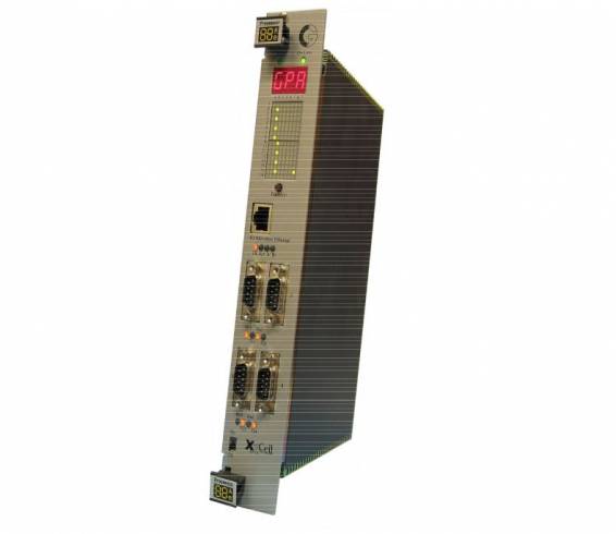
The CPR-041 Cell Processor Module has excellent communications capabilities. It supports four serial communications ports, each utilizing an industry standard 9-way D-type connector, plus a 10/100 Base-T Ethernet port utilizing a standard RJ-45 connector.
The four serial ports support the RS-232 standard and port numbers two and four are software selectable between the RS-232, RS422 and RS-485 standards. NOTE: The A & B markings on RS485 & RS422 may differ on other devices and you may need to experiment with the polarity (i.e. reverse the wires) to get the link to operate.
Serial ports 1 and 2 can support bit rates of up to 38,400 baud and serial ports 3 and 4 can support bit rates up to 115,200 bits per second.
Each port supports the standard modem signals, Transmit Data (TxD), Receive Data (RxD), Request to Send (RTS) and Clear to Send (CTS). Data Carrier Detected (DCD) is also supported on Ports 3 and 4. Rx and TX LEDs are provided for each serial port and located below the port as shown in the diagram below.
All 4 serial ports can be used for protocol communications; however, port 1 is usually reserved for diagnostics and configuration. The default usage of each port is as follows:
Connector 1 Monitor / Flash Download / Workbench Configuration / Protocol 1
Connector 2 Protocol 2
Connector 3 Protocol 3
Connector 4 Protocol 4
The diagram below shows the port designations on the CPR-041 front panel. The connections are summarized in the tables to the right.
LEDs are provided for the Ethernet interface with the following functionality:
LK Link Connected
Act Rx/Tx Activity LED
- 10Mbit / 100Mbit Mode (ON = 100Mbit; OFF = 0Mbit)
- Unused